Mesh Simplification and Polygon
Reduction
By Jonathan DeKlotz
Motivation
A mesh’s polygon-count has a big effect on the speed at which the mesh can be rendered in real time. Thus, a common goal among 3D modeling artists who make models for games and other real-time graphics applications is to make the model as realistic as possible while still minimizing the polygon-count. My project focuses on this issue. I have created a mesh simplification utility program I call “OptiMesh” (actually, I just did a google search for “optimesh” and there are a number of different products available under the name OptiMesh, including a professional mesh optimizer! Oh well, I guess unique clever names are hard to come by these days!). Although the program is far from being considered an industrial strength mesh optimizer, it demonstrates the basic concepts of mesh simplification and polygon reduction.
Program Overview
My program takes a high-poly mesh and progressively calculates low-poly meshes based on the geometry of the high-poly mesh. I wrote the program by creating dialog-style window that extends Microsoft’s MFC GUI library and I placed an OpenGL display frame in it along with some GUI controls for user interaction. The GUI includes a slider bar that allows the user to determine the amount of simplification to apply to the mesh. There are also a number of options and functions that the user is given control over through the interface.
Most of the program is entirely object oriented, and I make use of the many features of object orientation such as inheritance and polymorphism. Most classes are built with the “client-server” framework in mind. The main dialog box class, OptiMeshDlg, acts as the client in most cases, however, COpenGLWnd acts as both a client and a server (it serves the OptiMeshDlg class but is a client to JRDMesh and JRDSimpleMesh).
My program can load and save meshes in two different file formats (.m and .jbm). .m files are the ASCII files used in our class and .jbm files are of an alternative binary file format I created. The only benefit to .jbm files is that they load and save faster.
The underlying data structure used to hold the mesh data is one of the core concepts in the program. It is a dynamic data structure that utilizes many fundamental data structures such as trees, priority queues, linked lists, and stacks. I designed this data structure to have the ability to dynamically expand and contract. The source code behind the structure is very complicated, and I’ll explain the general concepts in more detail below.
When a mesh is loaded into the program, the user can slide the slider bar horizontally to progressively simplify the mesh. Large mesh files may take a long time to simplify, so the slider bar won’t act smoothly in real time as much as it does with smaller mesh files. The 2000 face gargoyle mesh, for instance, will simplify progressively quite smoothly, but the 10000 face dragon will take longer between simplifications, so the relative smoothness of the slider bar suffers. One thing to note, however, is that as the mesh is simplified, the simplification process speeds up.
My program allows the user to slide the “simplification slider bar” both ways. In other words, when you slide the bar back to the left, my program progressively rebuilds the mesh. The rebuilding process is much faster than the simplification process because most of the information needed to rebuild the mesh is computed during the simplification process.
Using the Program
Running the Program
Simply run the executable. I designed the main window on a computer with 1280 by 1024 screen resolution. It will still work in 1024 by 768, but part of the window will be cut off.
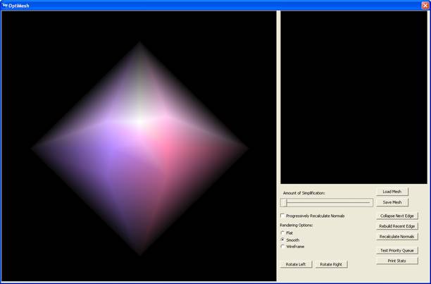
This is what the program
looks like when you start it up. It automatically loads a default mesh. I
created this mesh as a simple mesh to test my algorithms on.
Loading and Saving
Mesh Files
My program works with two different file formats (.m and .jbm). .m files are ASCII files that first list all the vertices in a mesh with an ID number and then all the faces. .jbm files are my own binary mesh file format files. Its much like the .m format except the data is stored in the file as binary data rather than readable text. .jbm files also store extra information that allow the mesh to be loaded faster.
Notice the “Load Mesh” and “Save Mesh” buttons in the program’s interface. Simply click either button to load or save the mesh at any time.
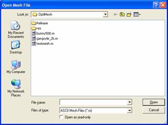
This is the load mesh dialog
window. It works like any other program in windows does. You can click cancel
and no mesh will be loaded (the one you already had loaded doesn’t close).
Also, select the file type in the drop-down list to switch between loading .m
files and .jbm files.
Changing Rendering
Options
Changing rendering options is simple, just choose between flat, smooth, and wireframe and click on the respective radio button on the interface. Also, to view the mesh at different angles, click on rotate left or rotate right.
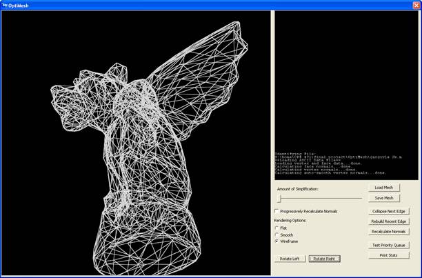
Here’s a screenshot
demonstrating wireframe mode and rotation. Notice the nice anti-aliased lines!
Simplifying the Mesh
To simplify the mesh quickly, you can click and drag the slider bar in the interface. Dragging it to the right simplifies the mesh. As you drag the slider bar, the terminal output window tells you how many faces are in the mesh. Dragging the bar all the way to the right simplifies the mesh as much as possible.
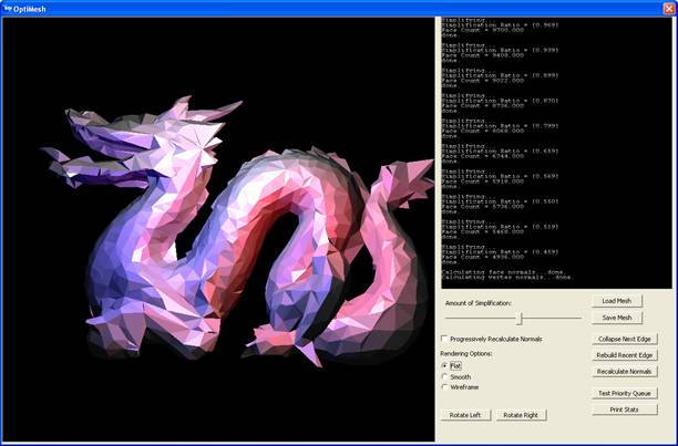
This screenshot shows the
10,000 face dragon mesh simplified to fewer than 5,000 faces.
While simplifying, the orientation of each modified face actually changes, so new vertex and face normals need to be recalculated in the changed areas of the surface. If the “Progressively Recalculate Normals” check box is checked, then all the appropriate normals are calculated during simplification. This does, however, slow down the simplification process. You can uncheck the check box to disable this feature and when done simplifying, click on the “Recalculate Normals” button, which just recalculates the normals for the entire mesh.
Also, two buttons, “Collapse Next Edge” and “Rebuild Recent Edge” collapse or rebuild one edge at a time. When collapsing or rebuilding edges one at a time, extra output is displayed in the terminal output window showing how the core data structure was modified.
The “Print Stats” button just displays the number of faces in the mesh in the terminal output window.
The “Test Priority Queue” button iterates through the entire priority queue. It outputs the number of edges that are in the queue. This is the number of edges left that can be collapsed.
Under the Hood
The Data Structure
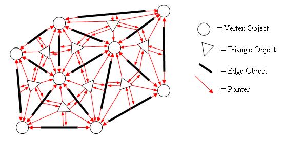
The data structure used to hold the mesh’s data is quite complex. I use two different classes, one which inherits the other, to describe the entire framework for the data structure. The class JRDMesh defines the Vertex, Triangle, and Edge structures. Every Vertex object keeps its own list of adjacent triangles (declared as a linked list of pointers to Triangle objects) in addition to its own data (3D position and vertex normal). The Triangle objects all contain pointers to their three vertices (three pointers to Vertex objects) and pointers to their three edges (three pointers to Edge objects). Edge objects have pointers to two Vertex objects and pointers to both of the edge’s adjacent Triangle objects. If this is hard to visualize, I drew a diagram to help visualize the structure (the red arrows signify pointers):
[if the diagram doesn’t display properly, I also made a jpeg image you can see by clicking here]
![]()
The only thing I left out of
this diagram is the pointer list for each Vertex
object to all of its adjacent Triangle
objects. I figured that would make the diagram too cluttered (if it isn’t
alreadyJ).
The Classes
The core data structure described above is encapsulated in the JRDMesh class. It is a sufficient structure to dynamically contain a mesh of arbitrary size and structure, and JRDMesh implements methods to load a mesh from a file, build the structure, and display it using OpenGL.
JRDMesh also keeps several other simpler data structures to make it easier to find different components of the main structure. A Map is used to store pairs of vertices and edges (the map key is a pair of Vertex pointers, and the element is an Edge pointer). This allows any edge to be located with logarithmic efficiency if its vertices are known, since the Map is implemented with a Tree structure. Also, simple linked lists are used to store all the triangles and edges, so that they can be easily iterated through.
The JRDMesh class, however, knows nothing about mesh simplification. I could have modified it further to include simplification, but I made a design decision not to do so because JRDMesh seemed like it embodied a complete concept by itself. Instead, I created a new class, JRDSimpleMesh, that is derived from JRDMesh. Thus, JRDSimpleMesh has all the capabilities of the JRDMesh class, and I could override some of JRDMesh’s methods and add new ones in order to implement mesh simplification.
JRDMesh defines all of the core data structure components (Vertex, Edge, and Triangle) as inner structures within JRDMesh’s class declaration. One of these structures, Edge needs to be modified in JRDSimpleMesh in order for the simplification algorithm (described below) to work. In order to do this, I derived a new structure SimpleEdge from Edge inside the class declaration of JRDSimpleMesh. A SimpleEdge is exactly like an edge except it has an added component, priority (this is elaborated on below in the description of the simplification algorithm).
The main methods JRDSimpleMesh implements are CollapseEdge() and ResurrectEdge(), which are the essential components of the mesh simplification algorithm. JRDSimpleMesh also overrides parts of the data structure creation routines originally defined in JRDMesh to insert SimpleEdges instead of just Edges. The beauty of it is that all the original routines in JRDMesh that are inherited and used (not overridden) by JRDSimpleMesh still work in their unmodified state due to the polymorphistic benefits of object orientation (you can refer to a SimpleEdge by a pointer to its base structure, Edge). In other words, the routines defined in JRDMesh that deal with edges think they’re dealing with Edge objects, when in reality they’re dealing with SimpleEdge objects.
The Algorithm
The algorithm I implemented is based on a concept called “edge decimation”. Two other concepts known as “vertex decimation” and “triangle” decimation are other alternative approaches to mesh simplification.
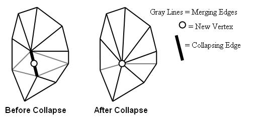
With edge decimation, my method of choice, polygons are removed from the mesh by collapsing edges. Collapsing an edge in a mesh effectively removes two triangles from an area of the mesh’s surface. Conceptually, the two vertices of the edge are merged into one, and the triangle adjacency lists of the two original vertices are concatenated for the new vertex. I have drawn a diagram to illustrate this:
[if the diagram doesn’t display properly, I also made a jpeg image you can see by clicking here]
Because this process has to be reversible, every time I collapse an edge and merge the triangle adjacency lists, I store enough information to split the concatenated list back into the two lists for each of the collapsed edge’s vertices.
The routine for collapsing an edge and rebuilding an edge has to be general enough to work for an arbitrary area of the mesh’s surface. For instance, some models don’t guarantee that every edge has two adjacent triangles (in other words, there is an actual “edge” in the surface where the surface stops and is not continuous). In these meshes, my edge collapsation function would break down if it did not check to make sure that the collapsing edge had exactly two adjacent triangles. In fact, there are a number of different cases where you don’t want to collapse an edge. When a collapsed edge creates a situation with more than one edge between any two vertices or more than two faces adjacent to any edge, the collapsing edge must be prevented from collapsing. My program does all of the preceding checks before collapsing an edge.
Reversibility
As already mentioned, the algorithm is reversible. For every edge collapsed, a chunk of data is computed and pushed onto a stack. I have aptly named this data chunk EdgeCorpse. It keeps a pointer to the collapsed edge, which in turn keeps the pointers to the collapsed triangles and the removed vertex. When an edge and its adjacent triangles are collapsed and one of the edge’s vertices are removed, nothing else in the whole program references them (i.e. has a pointer pointing to them) except for the corresponding EdgeCorpse object that now resides on the stack (in my code I name my stack the edgeCorpsePile J). In other words, the mesh data structure itself and the code that draws it has no idea that there are collapsed edges on a stack waiting to be reinserted.
JRDSimpleMesh implements both the CollapseEdge() and ResurrectEdge() functions, where CollapseEdge() is responsible for collapsing an edge, building an EdgeCorpse data chunk, and pushing the chunk onto the stack, and ResurrectEdge() is responsible for popping an EdgeCorpse data chunk off the stack and rebuilding the edge. Subsequent calls to CollapseEdge() and ResurrectEdge() leave the core data structure unchanged. The reason I used a stack for storing the EdgeCorpse data chunks is because in order to rebuild the mesh properly, edges must be rebuilt in exactly the same order they are collapsed.
CollapseEdge() and ResurrectEdge() are not trivial functions by any means. Take one look at my diagram of the core data structure above and try to visualize how an edge might be collapsed. There are numerous pointers referencing the edge and the two triangles collapsed by the edge and the vertex adjacency lists have to be recomputed in the changed surface region. Also, the diagram above only demonstrates a very simple example of a mesh’s surface with a maximum of five adjacent triangles per vertex. CollapseEdge() and ResurrectEdge() have to be written to work with any mesh surface structure.
Conclusions
Short-comings
I had a lot of ideas for mesh optimization that I didn’t have time for. I originally planned to include a bump map generator that would generate a bump map for the simplified meshes based on the geometry of the original, unsimplified mesh. I plan to continue working on the program and eventually implement this.
I implemented the most basic edge prioritizing routines, based on edge length. There are a lot of other better ways to prioritize edges such as minimizing change in volume. Again, I plan to implement this eventually.
Also, I currently collapse edges down to a vertex which is calculated simply by finding the midpoint between the collapsing edge’s vertices. Simply put, there are much better, more complicated ways of calculating new vertex locations that result in a more accurate mesh simplification.
I need to read a whole book on MFC and Win32 programming. I was unable to get keyboard or mouse input working the way I wanted it to.
Triumphs
I successfully set up OpenGL to display in a portion of a dialog window (no GLUT used here).
I programmed the nice looking console-style output window myself. This, alone, was a significant accomplishment. It uses a bitmap stored in memory of all the ASCII characters and does a number of bit blits to move pixels around to assemble the displayed text. It even does my own version of double-buffering!
I actually successfully programmed a dynamic mesh data structure from the ground up. The accomplishments I’m the most proud of are the edge collapsation function and the whole reversibility mechanism, which I thought up on my own.
After reading some published papers on the general mesh
simplification concepts, I came up with all the implementation ideas on my own
(except for the priority queue idea, which is a really common way of sorting
the edges), and I think it came out quite nicely.